
![]()
For those just joining us….
AV1 is a new general-purpose video codec developed by the Alliance for Open Media. The alliance began development of the new codec using Google’s VPX codecs, Cisco’s Thor codec, and Mozilla’s/Xiph.Org’s Daala codec as a starting point. AV1 leapfrogs the performance of VP9 and HEVC, making it a next-next-generation codec . The AV1 format is and will always be royalty-free with a permissive FOSS license.
This post was written originally as the second in an in-depth series of posts exploring AV1 and the underlying new technologies deployed for the first time in a production codec. An earlier post on the Xiph.org website looked at the Chroma from Luma prediction feature. Today we cover the Constrained Directional Enhancement Filter. If you’ve always wondered what goes into writing a codec, buckle your seat-belts, and prepare to be educated!
Filtering in AV1
Virtually all video codecs use enhancement filters to improve subjective output quality.
By ‘enhancement filters’ I mean techniques that do not necessarily encode image information or improve objective coding efficiency, but make the output look better in some way. Enhancement filters must be used carefully because they tend to lose some information, and for that reason they’re occasionally dismissed as a deceptive cheat used to make the output quality look better than it really is.
But that’s not fair. Enhancement filters are designed to mitigate or eliminate specific artifacts to which objective metrics are blind, but are obvious to the human eye. And even if filtering is a form of cheating, a good video codec needs all the practical, effective cheats it can deploy.
Filters are divided into multiple categories. First, filters can be normative or non-normative. A normative filter is a required part of the codec; it’s not possible to decode the video correctly without it. A non-normative filter is optional.
Second, filters are divided according to where they’re applied. There are preprocessing filters, applied to the input before coding begins, postprocessing filters applied to the output after decoding is complete, and in-loop or just loop filters that are an integrated part of the encoding process in the encoding loop. Preprocessing and postprocessing filters are usually non-normative and external to a codec. Loop filters are normative almost by definition and part of the codec itself; they’re used in the coding optimization process, and applied to the reference frames stored or inter-frame coding.
 AV1 uses three normative enhancement filters in the coding loop. The first, the deblocking filter, does what it says; it removes obvious bordering artifacts at the edges of coded blocks. Although the DCT is relatively well suited to compacting energy in natural images, it still tends to concentrate error at block edges. Remember that eliminating this blocking tendency was a major reason Daala used a lapped transform, however AV1 is a more traditional codec with hard block edges. As a result, it needs a traditional deblocking filter to smooth the block edge artifacts away.
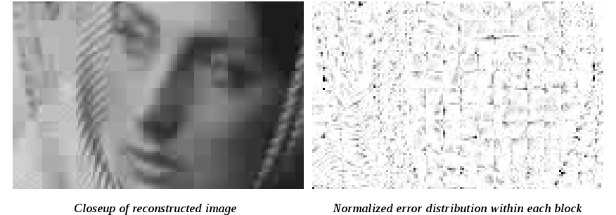
An example of blocking artifacts in a traditional DCT block-based codec. Errors at the edges of blocks are particularly noticeable as they form hard edges. Worse, the DCT (and other transforms in the DCT family) tend to concentrate error at block edges, compounding the problem.
The last of the three filters is the Loop Restoration filter. It consists of two configurable and switchable filters, a Wiener filter and a Self-Guided filter. Both are convolving filters that try to build a kernel to restore some lost quality of the original input image and are usually used for denoising and/or edge enhancement. For purposes of AV1, they’re effectively general-purpose denoising filters that remove DCT basis noise via a configurable amount of blurring.
The filter between the two, the Constrained Directional Enhancement Filter (CDEF) is the one we’re interested in here; like the loop restoration filter, it removes ringing and basis noise around sharp edges, but unlike the loop restoration filter, it’s directional. It can follow edges, as opposed to blindly filtering in all directions like most filters. This makes CDEF especially interesting; it’s the first practical and useful directional filter applied in video coding.
The Long and Winding Road
The CDEF story isn’t perfectly linear; it’s long and full of backtracks, asides, and dead ends. CDEF brings multiple research paths together, each providing an idea or an inspiration toward the final Constrained Directional Enhancement Filter in AV1. The ‘Directional’ aspect of CDEF is especially novel in implementation, but draws ideas and inspiration from several different places.
The whole point of transforming blocks of pixel data using the DCT and DCT-like transforms is to represent that block of pixels using fewer numbers. The DCT is pretty good at compacting the energy in most visual images, that is, it tends to collect spread out pixel patterns into just a few important output coefficients.
There are exceptions to the DCT’s compaction efficiency. To name the two most common examples, the DCT does not represent directional edges or patterns very well. If we plot the DCT output of a sharp diagonal edge, we find the output coefficients also form…. a sharp diagonal edge! The edge is different after transformation, but it’s still there and usually more complex than it started. Compaction defeated!
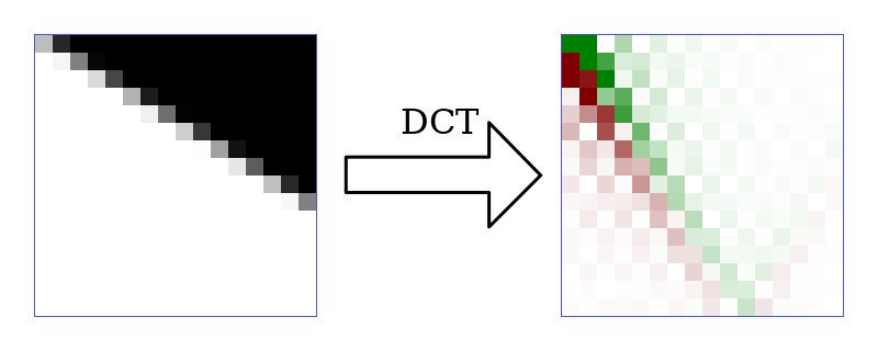
Sharp features are a traditional problem for DCT-based codecs as they do not compact well, if at all. Here we see a sharp edge (left) and its DCT transform coefficients (right). The energy of the original edge is spread through the DCT output in a directional rippling pattern.
Over the past two decades, video codec research has increasingly looked at transforms, filters, and prediction methods that are inherently directional as a way of better representing directional edges and patterns, and correcting this fundamental limitation of the DCT.
Classic Directional Predictors
Directional intra prediction is probably one of the best known directional techniques used in modern video codecs. We’re all familiar with h.264’s and VP9’s directional prediction modes, where the codec predicts a directional pattern into a new block, based on the surrounding pixel pattern of already decoded blocks. The goal is to remove (or greatly reduce) the energy contained in hard, directional edges before transforming the block. By predicting and removing features that can’t be compacted, we improve the overall efficiency of the codec.

Illustration of directional prediction modes available in AVC/H.264 for 4×4 blocks. The predictor extends values taken from a one-pixel-wide strip of neighboring pixels into the predicted block in one of eight directions, plus an averaging mode for simple DC prediction.
Motion compensation, an even older idea, is also a form of directional prediction, though we seldom think of it that way. It displaces blocks in specific directions, again to predict and remove energy prior to the DCT. This block displacement is directional and filtered, and like directional intra-prediction, uses carefully constructed resampling filters when the displacement isn’t an integer number of pixels.
Directional Filters
As noted earlier, video codecs make heavy use of filtering to remove blocking artifacts and basis noise. Although the filters work on a 2D plane, the filters themselves tend to be separable, that is, they’re usually 1D filters that are run horizontally and vertically in separate steps.
Directional filtering attempts to run filters in directions besides just horizontal and vertical. The technique is already common in image processing, where noise removal and special effects filters are often edge- and direction-aware. However, these directional filters are often based on filtering the output of directional transforms, for example, the [somewhat musty] image denoising filters I wrote based on dual-tree complex wavelets.
The directional filters in which we’re most interested for video coding need to work on pixels directly, following along a direction, rather than filtering the frequency-domain output of a directional transform. Once you try to design such a beast, you quickly hit the first Big Design Question: how do you ‘follow’ directions other than horizontal and vertical, when your filter tap positions no longer land squarely on pixels arranged in a grid?
One possibility is the classic approach used in high-quality image processing: transform the filter kernel and resample the pixel space as needed. One might even argue this is the only ‘correct’ or ‘complete’ answer. It’s used in subpel motion compensation, which cannot get good results without at least decent resampling, and in directional prediction which typically uses a fast approximation.
That said, even a fast approximation is expensive when you don’t need to do it, so avoiding the resampling step is a worthy goal if possible. The speed penalty is part of the reason we’ve not seen directional filtering in video coding practice.
Directional Transforms
Directional transforms attempt to fix the DCT’s edge compaction problems in the transform itself.
Experimental directional transforms fall into two categories. There are the transforms that use inherently directional bases, such as directional wavelets. These transforms tend to be oversampled/overcomplete, that is, they produce more output data than they take input data— usually massively more. That might seem like working backwards; you want to reduce the amount of data, not increase it! But these transforms still compact the energy, and the encoder still chooses some small subset of the output to encode, so it’s really no different from usual lossy DCT coding. That said, overcomplete transforms tend to be expensive in terms of memory and computation, and for this reason, they’ve not taken hold in mainstream video coding.
The second category of directional transform takes a regular, non-directional transform such as the DCT, and modifies it by altering the input or output. The alteration can be in the form of resampling, a matrix multiplication (which can be viewed as a specialized form of resampling), or juggling of the order of the input data.
It’s this last idea that’s the most powerful, because it’s fast. There’s no actual math to do when simply rearranging numbers.
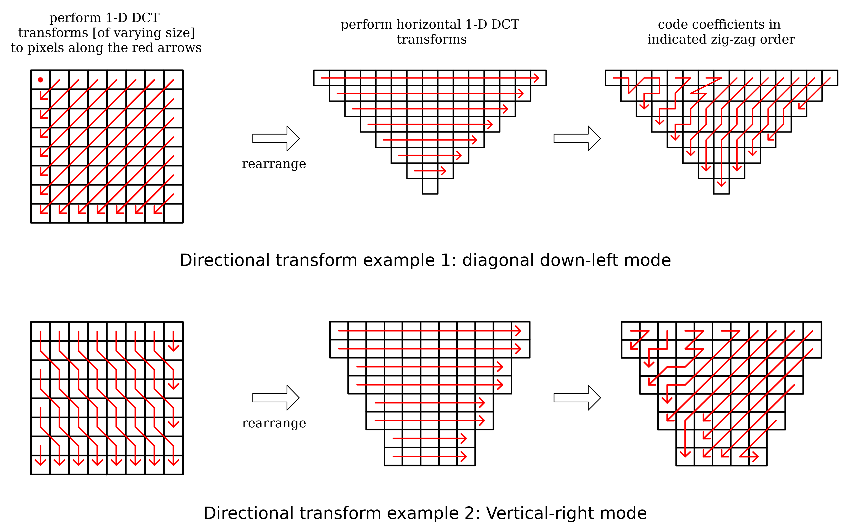
Two examples implementing a directional transforms in different directions using pixel and coefficient reshuffling, rather than a resampling filter. This example is from An Overview of Directional Transforms in Image Coding, by Xu, Zeng, and Wu.
A few practical complications make implementation tricky. Rearranging a square to make a diagonal edge into a [mostly] vertical or horizontal line results in a non-square matrix of numbers as an input. Conceptually, that’s not a problem; the 2D DCT is separable, and since we can run the row and column transforms independently, we can simply use different sized 1D DCTs for each length row and column, as in the figure above. In practice this means we’d need a different DCT factorization for every possible column length, and shortly after realizing that, the hardware team throws you out a window.
There are also other ways of handling the non-squareness of a rearrangement, or coming up with resampling schemes that keep the input square or only operate on the output. Most of the directional transform papers mentioned below are concerned with the various schemes for doing so.
But here’s where the story of directional transforms mostly ends for now. Once you work around the various complications of directional transforms and deploy something practical, they don’t work well in a modern codec for an unexpected reason: They compete with variable blocksize for gains. That is, in a codec with a fixed blocksize, adding directional transforms alone gets impressive efficiency gains. Adding variable blocksize alone gets even better gains. Combining variable blocksize and directional transforms gets no benefit over variable blocksize alone. Variable blocksize has already effectively eliminated the same redundancies exploited by directional transforms, at least the ones we currently have, and done a better job of it.
Nathan Egge and I both experimented extensively with directional transforms during Daala research. I approached the problem from both the input and output side, using sparse matrix multiplications to transform the outputs of diagonal edges into a vertical/horizontal arrangement. Nathan ran tests on mainstream directional approaches with rearranged inputs. We came to the same conclusion: there was no objective or subjective gain to be had for the additional complexity.
Directional transforms may have been a failure in Daala (and other codecs), but the research happened to address a question posed earlier: How to filter quickly along edges without a costly resampling step? The answer: don’t resample. Approximate the angle by moving along the nearest whole pixel. Approximate the transformed kernel by literally or conceptually rearranging pixels. This approach introduces some aliasing, but it works well enough, and it’s fast enough.
Directional Predictors, part 2: The Daala Chronicles
The Daala side of the CDEF story began while trying to do something entirely different: normal, boring, directional intra-prediction. Or at least what passed for normal in the Daala codec.
I wrote about Daala’s frequency-domain intra prediction scheme at the time we were just beginning to work on it. The math behind the scheme works; there was never any concern about that. However, a naive implementation requires an enormous matrix multiplication that was far too expensive for a production codec. We hoped that sparsifying— eliminating matrix elements that didn’t contribute much to the prediction— could reduce the computational cost to a few percent of the full multiply.
Sparsification didn’t work as hoped. At least as we implemented it, sparsification simply lost too much information for the technique to be practical.
Of course, Daala still needed some form of intra-prediction, and Jean-Marc Valin had a new idea: A stand-alone prediction codec, one that worked in the spatial domain, layered onto the frequency-domain Daala codec. As a kind of symbiont that worked in tandem with but had no dependencies on the Daala codec, it was not constrained by Daala’s lapping and frequency domain requirements. This became Intra Paint.

An example of the Intra Paint prediction algorithm as applied to a photograph of Sydney Harbor. The visual output is clearly directional and follows the edges and features in the original image well, producing a pleasing (if somewhat odd) result with crisp edges.
The way intra paint worked was also novel; it coded 1-dimensional vectors along only the edges of blocks, then swept the pattern along the selected direction. It was much like squirting down a line of colored paint dots, then sweeping the paint in different directions across the open areas.
Intra paint was promising and produced some stunningly beautiful results on its own, but again wasn’t efficient enough to work as a standard intra predictor. It simply didn’t gain back enough bits over the bits it had to use to code its own information.
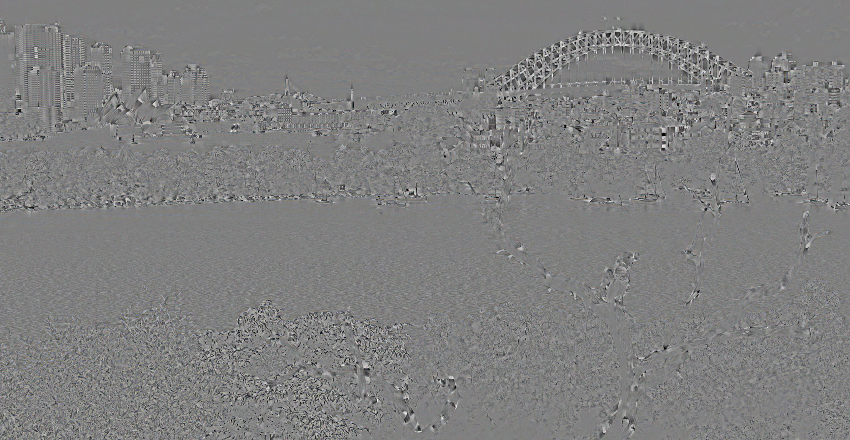
Difference between the original Sydney Harbor photo and the Intra Paint result. Despite the visually pleasing output of Intra Paint, we see that it is not an objectively super-precise predictor. The difference between the original photo and the intra-paint result is fairly high, even along many edges that it appeared to reproduce well.
The intra paint ‘failure’ again planted the seed of a different idea; although the painting may not be objectively precise enough for a predictor, much of its output looked subjectively quite good. Perhaps the paint technique could be used as a post-processing filter to improve subjective visual quality? Intra paint follows strong edges very well, and so could potentially be used to eliminate basis noise that tends to be strongest along the strongest edges. This is the idea behind the original Daala paint-deringing filter, which eventually leads to CDEF itself.
There’s one more interesting mention on the topic of directional prediction, although it too is currently a dead-end for video coding. David Schleef implemented an interesting edge/direction aware resampling filter called Edge-Directed Interpolation (EDI). Other codecs (such as the VPx series and for a while AV1) have experimented with downsampled reference frames, transmitting the reference in a downsampled state to save coding bits, and then upsampling the reference for use at full resolution. We’d hoped that much-improved upsampling/interpolation provided by EDI would improve the technique to the point it was useful. We also hoped to use EDI as an improved subpel interpolation filter for motion compensation. Sadly, those ideas remain an unfulfilled dream.
Bridging the Gap, Merging the Threads
At this point, I’ve described all the major background needed to approach CDEF, but chronologically the story involves some further wandering in the desert. Intra paint gave rise to the original Daala paint-dering filter, which reimplemented the intra-paint algorithm to perform deringing as a post-filter. Paint-dering proved to be far too slow to use in production.
As a result, we packed up the lessons we learned from intra paint and finally abandoned the line of experimentation. Daala imported Thor’s CLPF for a time, and then Jean-Marc built a second, much faster Daala deringing filter based on the intra-paint edge direction search (which was fast and worked well) and a Conditional Replacement Filter. The CRF is inspired somewhat by a median filter and produces results similar to a bilateral filter, but is inherently highly vectorizable and therefore much faster.
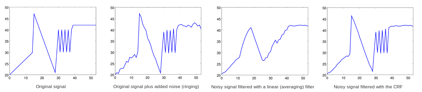
Demonstration of a 7-tap linear filter vs the constrained replacement filter as applied to a noisy 1-dimensional signal, where the noise is intended to simulate the effects of quantization on the original signal.
The final Daala deringing filter used two 1-dimensional CRF filters, a 7-tap filter run in the direction of the edge, and a weaker 5-tap filter run across it. Both filters operate on whole pixels only, performing no resampling. At that point, the Daala deringing filter began to look a lot like what we now know as CDEF.
We’d recently submitted Daala to AOM as an input codec, and this intermediate filter became the AV1 daala_dering experiment. Cisco also submitted their own deringing filter, the Constrained Low-Pass Filter (CLPF) from the Thor codec. For some time the two deringing filters coexisted in the AV1 experimental codebase where they could be individually enabled, and even run together. This led both to noticing useful synergies in their operation, as well as additional similarities in various stages of the filters.
And so, we finally arrive at CDEF: The merging of Cisco’s CLPF filter and the second version of the Daala deringing filter into a single, high-performance, direction-aware deringing filter.
Modern CDEF
The CDEF filter is simple and bears a deep resemblance to our preceding filters. It is built out of three pieces (directional search, the constrained replacement/lowpass filter, and integer-pixel tap placement) that we’ve used before. Given the lengthy background preamble to this point, you might almost look at the finished CDEF and think, “Is that it? Where’s the rest?” CDEF is an example of gains available by getting the details of a filter exactly right as opposed to just making it more and more complex. Simple and effective is a good place to be.
Direction search
CDEF operates in a specific direction, and so it is necessary to determine that direction. The search algorithm used is the same as from intra paint and paint-dering, and there are eight possible directions.
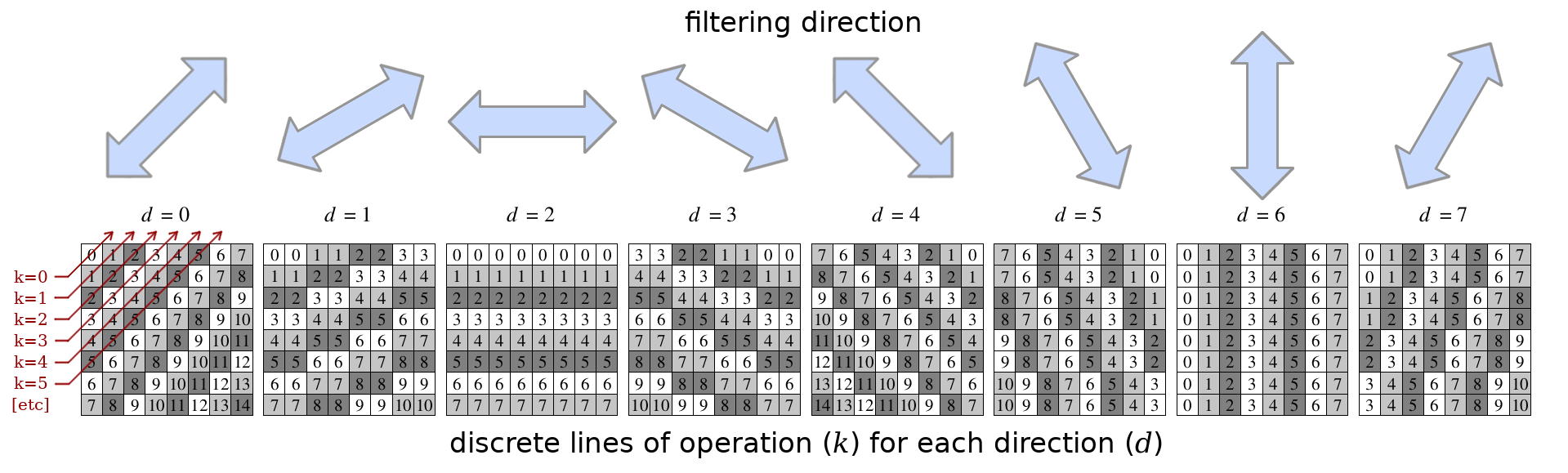
The eight possible filtering directions of the current CDEF filter. The numbered lines in each directional block correspond to the ‘k’ parameter within the direction search.
We determine the filter direction by making “directional” variants of the input block, one for each direction, where all of the pixels along a line in the chosen direction are forced to have the same value. Then we pick the direction where the result most closely matches the original block. That is, for each direction d, we first find the average value of the pixels in each line k, and then sum, along each line, the squared error between a given pixel value and the average value of that pixel line.
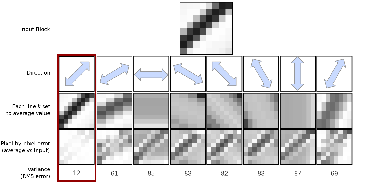
An example process of selecting the direction d that best matches the input block. First we determine the average pixel value for each line of operation k for each direction. This is illustrated above by setting each pixel of a given line k to that average value. Then, we sum the error for a given direction, pixel by pixel, by subtracting the input value from the average value. The direction with the lowest error/variance is selected as the best direction.
This gives us the total squared error, and the lowest total squared error is the direction we choose. Though the pictured example above does so, there’s no reason to convert the squared error to variance; each direction considers the same number of pixels, so both will choose the same answer. Save the extra division!
This is the intuitive, long-way-around to compute the directional error. We can simplify the mechanical process down to the following equation: 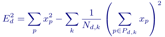 In this equation, E is the error, p is a pixel, xp is the value of a pixel, k is one of the numbered lines in the directional diagram above, and Nd,k is the cardinality of (the number of pixels in) the line k for direction d. This equation can be simplified in practice; for example the first term is the same for each given d. In the end, the AV1 implementation of CDEF currently requires 5.875 additions and 1.9375 multiplications per pixel and can be deeply vectorized, resulting in a total cost less than an 8×8 DCT.
Filter taps
The CDEF filter works pixel-by-pixel across a full block. The direction d selects the specific directional filter to be used, each consisting of a set of filter taps (that is, input pixel locations) and tap weights.
CDEF conceptually builds a directional filter out of two 1-dimensional filters. A primary filter is run along the chosen direction, like in the Daala deringing filter. The secondary filter is run twice in a cross-pattern, at 45° angles to the primary filter, like in Thor’s CLPF.
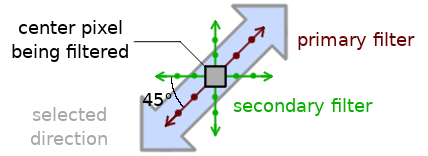
Illustration of primary and secondary 1-D filter directionality in relation to selected direction d. The primary filter runs along the selected filter direction, the secondary filters run across the selected direction at a 45° angle. Every pixel in the block is filtered identically.
The filters run at angles that often place the ideal tap locations between pixels. Rather than resampling, we choose the nearest exact pixel location, taking care to build a symmetric filter kernel.
Each tap in a filter also has a fixed weight. The filtering process takes the input value at each tap, applies the constraint function, multiplies the result by the tap’s fixed weight, and then adds this output value to the pixel being filtered.
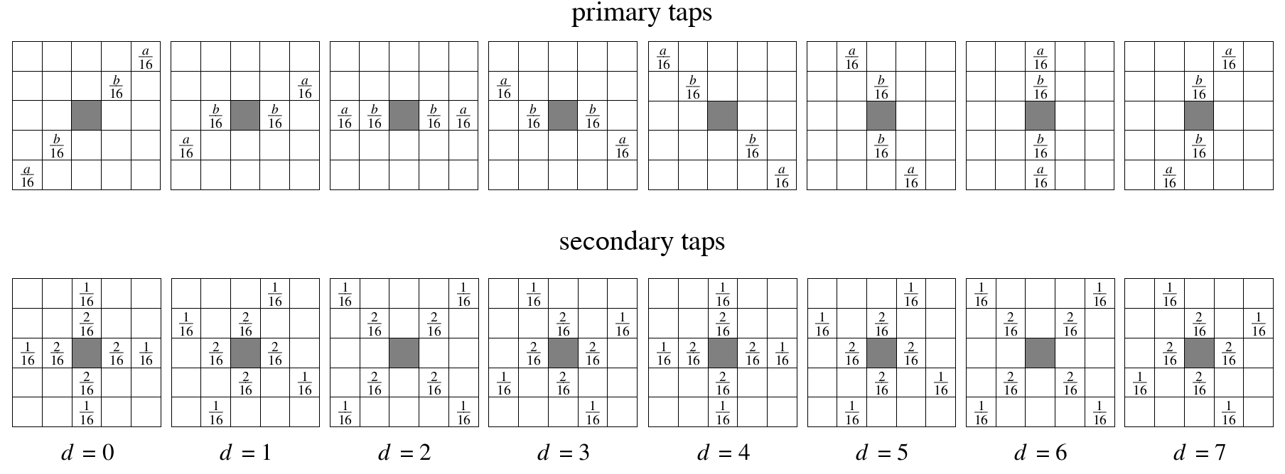
Primary and secondary tap locations and fixed weights (w) by filter direction. For primary taps and even Strengths a = 2 and b = 4, whereas for odd Strengths a = 3 and b = 3. The filtered pixel in shown in gray.
In practice, the primary and secondary filters are not run separately, but combined into a single filter kernel that’s run in one step.
Constraint function
CDEF uses a constrained low-pass filter in which the value of each filter tap is first processed through a constraint function parameterized by the difference between the tap value and pixel being filtered d, the filter strength S, and the filter damping parameter D: 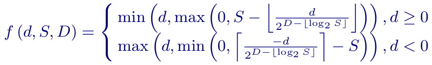 The constraint function is designed to deemphasize or outright reject consideration of pixels that are too different from the pixel being filtered. Tap value differences within a certain range from the center pixel value (as set by the Strength parameter S) are wholly considered. Value differences that fall between the Strength and Damping parameters are deemphasized. Finally, tap value differences beyond the Damping parameter are ignored.
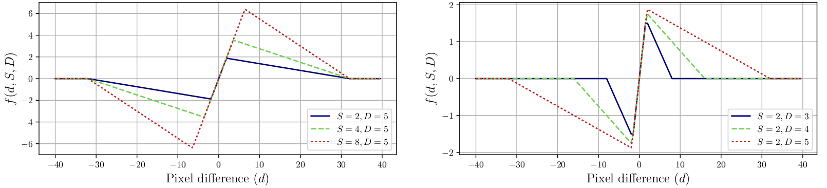
An illustration of the constraint function. In both figures, the difference (d) between the center pixel and the tap pixel being considered is along the x axis. The output value of the constraint function is along y. The figure on the left illustrates the effect of varying the Strength (S) parameter. The figure on the right demonstrates the effect of varying Damping (D).
The output value of the constraint function is then multiplied by the fixed weight associated with each tap position relative to the center pixel. Finally the resulting values (one for each tap) are added to the center filtered pixel, giving us the final, filtered pixel value. It all rolls up into: …where the introduced (p) and (s) mark values for the primary and secondary sets of taps.
There are a few additional implementation details regarding rounding and clipping not needed for understanding; if you’re intending to implement CDEF they can of course be found in the full CDEF paper.
Results
CDEF is intended to remove or reduce basis noise and ringing around hard edges in an image without blurring or damaging the edge. As used in AV1 right now, the effect is subtle but consistent. It may be possible to lean more heavily on CDEF in the future.
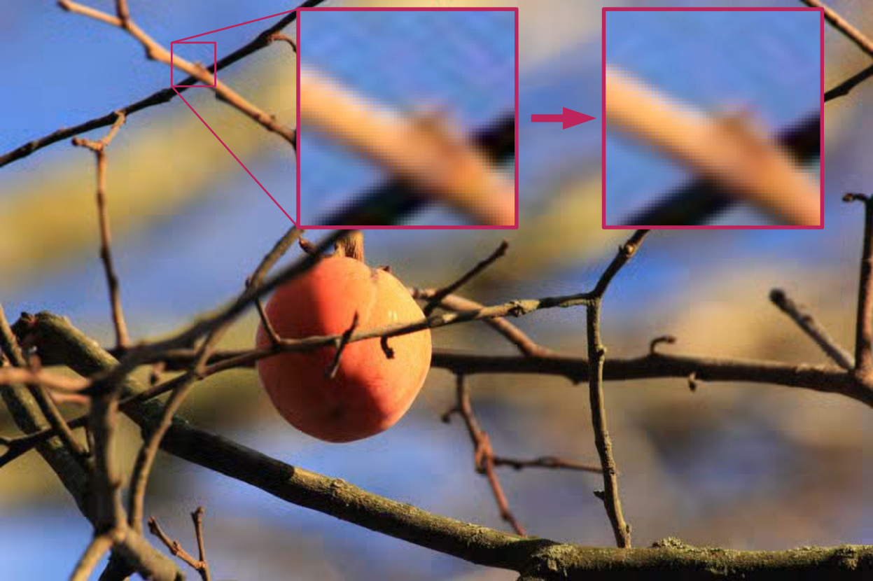
An example of ringing/basis noise reduction in an encode of the image Fruits. The first inset closeup shows the area without processing by CDEF, the second inset shows the same area after CDEF.
The quantitative value of any enhancement filter must be determined via subjective testing. Better objective metrics numbers as well wouldn’t exactly be shocking, but the kind of visual improvements that motivate CDEF are mostly outside the evaluation ability of primitive objective testing tools such as PSNR or SSIM.
As such, we conducted multiple rounds of subjective testing, first during the development of CDEF (when Daala dering and Thor CLPF were still technically competitors) and then more extensive testing of the merged CDEF filter. Because CDEF is a new filter that isn’t present at all in previous generations of codecs, testing primarily consisted of AV1 with CDEF enabled, vs AV1 without CDEF.
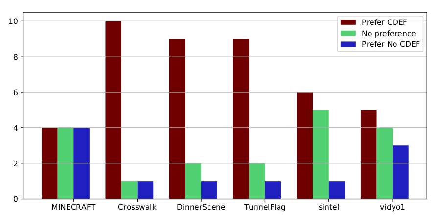
Subjective A-B comparison results (with ties) for CDEF vs. no CDEF for the high-latency configuration.
Subjective results show a statistically significant (p<.05) improvement for 3 out of 6 clips. This normally corresponds to a 5-10% improvement in coding efficiency, a fairly large gain for a single tool added to an otherwise mature codec.
Objective testing, as expected, shows more modest improvements of approximately 1%, however objective testing is primarily useful only insofar as it agrees with subjective results. Subjective testing is the gold standard, and the subjective results are clear.
Testing also shows that CDEF performs better when encoding with fewer codec ‘tools’; like directional transforms, CDEF is competing for coding gains with other, more-complex techniques within AV1. As CDEF is simple, small, and fast, it may provide future means to reduce the complexity of AV1 encoders. In terms of decoder complexity, CDEF represents between 3% and 10% of the AV1 decoder depending on the configuration.
Additional Resources
- Xiph.Org’s standard ‘derf’ test sets, hosted at media.xiph.org
- Automated testing harness and metrics used by Daala and AV1 development: Are We Compressed Yet?
- The AV1 Constrained Directional Enhancement Filter (CDEF)
Steinar Midtskogen, Jean-Marc Valin, October 2017 - CDEF Presentation Slide Deck for ICASSP 2018, Steinar Midtskogen, Jean-Marc Valin
- A Deringing Filter for Daala and Beyond, Jean-Marc Valin
This is an earlier deringing filter developed during research for the Daala codec that contributed to the CDEF used in AV1. - Daala: Painting Images For Fun and Profit, Jean-Marc Valin
A yet earlier intra-paint-based enhancement filter that led to the Daala deringing filter, which in turn led to CDEF - Intra Paint Deringing Filter, Jean-Marc Valin 2015
Notes on the enhancement/deringing filter built out of the Daala Intra Paint prediction experiment - Guided Image Filtering Kaiming He, Jian Sun, Xiaoou Tang, 2013
- Direction-Adaptive Discrete Wavelet Transform for Image Compression, Chuo-Ling Chang, Bernd Girod, IEEE Transactions on Image Processing, vol. 16, no. 5, May 2007
- Direction-adaptive transforms for image communication, Chuo-Ling Chang, Stanford PhD dissertation 2009
This dissertation presents a good summary of the state of the art of directional transforms in 2009; sadly it appears there are no online-accessible copies. - Direction-Adaptive Partitioned Block Transform for Color Image Coding, Chuo-Ling Chang, Mina Makar, Sam S. Tsai, Bernd Girod, IEEE Transactions on Image Processing, vol. 19, no. 7, July 2010
- Pattern-based Assembled DCT scheme with DC prediction and adaptive mode coding, Zhibo Chen, Xiaozhong Xu
Note this paper is behind the IEEE paywall - Direction-Adaptive Transforms for Coding Prediction Residuals, Robert A. Cohen, Sven Klomp, Anthony Vetro, Huifang Sun, Proceedings of 2010 IEEE 17th International Conference on Image Processing, September 26-29, 2010, Hong Kong
- An Orientation-Selective Orthogonal Lapped Transform, Dietmar Kunz 2008
Note this paper is behind the IEEE paywall. - Rate-Distortion Analysis of Directional Wavelets, Arian Maleki, Boshra Rajaei, Hamid Reza Pourreza, IEEE Transactions on Image Processing, vol. 21, no. 2, February 2012
- Theoretical Analysis of Trend Vanishing Moments for
Directional Orthogonal TransformsShogo Murumatsu, Dandan Han, Tomoya Kobayashi, Hisakazu Kikuchi
Note that this paper is behind the IEEE paywall. However a ‘poster’ version of the paper is freely available. - An Overview of Directional Transforms in Image Coding,
Jizheng Xu, Bing Zeng, Feng Wu - Directional Filtering Transform for Image/Intra-Frame Compression, Xiulian Peng, Jizheng Xu, Feng Wu, IEEE Transaction in Image Processing, Vol. 19, No. 11, November 2010
Note that this paper is behind the IEEE paywall. - Approximation and Compression with Sparse
Orthonormal Transforms, O. G. Sezer, O. G. Guleryuz, Yucel Altunbasak, 2008 - Robust Learning of 2-D Separable Transforms for Next-Generation Video Coding O. G. Sezer, R. Cohen, A. Vetro, March 2011
- Joint sparsity-based optimization of a set of orthonormal 2-D separable block transforms, Joel Sole, Peng Yin, Yunfei Zheng, Cristina Gomila, 2009
Note that this paper is behind the IEEE paywall. - Directional
Lapped Transforms for Image Coding,Jizheng Xu, Feng Wu, Jie Liang, Wenjun Zhang, IEEE Transactions on Image Processing, April 2008 - Directional Discrete Cosine Transforms—A New
Framework for Image Coding,Bing Zeng, Jingjing Fu, IEEE Transactions on Circuits and Systems for Video Technology, April 2008 - The Dual-Tree Complex Wavelet Transform, Ivan W. Selesnick, Richard G. Baraniuk, and Nick G. Kingsbury, IEEE Signal Processing Magazine, November 2005
4 comments